forum
library
tutorial
contact

Testing to Improve Fish Passage
Through the Ice Harbor Turbines
by Jason M. Foust, Martin Ahmann, Robert Davidson, Jim Kiel and Tom FreemanHydroWorld, May 20, 2014
|
the film forum library tutorial contact |
|
Testing to Improve Fish Passage
by Jason M. Foust, Martin Ahmann, Robert Davidson, Jim Kiel and Tom Freeman |
Substantial efforts are under way at the U.S. Army Corps of Engineers' 603-MW Ice Harbor hydropower project
in Washington State to improve survival of juvenile salmon and steelhead passing through the turbines.
 The U.S. Army Corps of Engineers manages the 603-MW Ice Harbor project to minimize the number of fish passing through the turbines. During periods of juvenile migration, a significant portion of the river flow spills over the dam, bypassing the turbines altogether. For the fish that do enter the turbine intakes, a series of screens placed upstream of the spiral case help guide fish into a vertical gate slot that provides a passage route to the tailrace. The number of juveniles that enter the turbine intakes and continue downstream past the screens depends on fish depth within the upper reservoir. Current turbine passage estimates for juvenile salmon and steelhead at Ice Harbor are 10% to 25%.
To improve safe fish passage, the Corps initiated a collaborative design effort with Voith Hydro to investigate new turbine runners, in addition to other Ice Harbor water passage modifications. This article discusses the Ice Harbor development process, including the use of physical model testing to evaluate the turbine passage environments that result from various design changes.
Project background
Funds for this design effort were provided by the Bonneville Power Administration (BPA) and Corps' Columbia River Fish Mitigation (CRFM) Program. The work is unique in that fish passage criteria, rather than turbine power and efficiency, make up the primary evaluation criteria. Fixed and adjustable blade runner designs are being investigated through the use of computational fluid dynamics (CFD) modeling to assess various fish passage criteria, including minimum pressures within the water passage, shear and overall flow quality, i.e. uniformity of flow. Early within the project, the information led to an improved stay vane design in the distributor. In addition, the computational results are utilized to evaluate blade shape changes aimed at reducing fish strike on the runner blades.
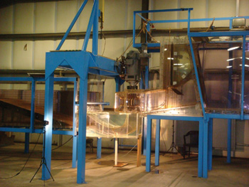
After the hydraulic shapes are defined for each iteration, model turbine components are manufactured and tested. Performance testing is conducted first at Voith Hydro's test facility in York, Pa., to document the performance characteristics of the modified turbine. When performance testing is complete, the runner and modified hydraulic shapes are installed at the Corps' Ice Harbor Froude test facility in Vicksburg, Miss., to evaluate fish passage.
Both the performance and observational models are manufactured at the same scale (1:25) so the runners are interchangeable. Power, efficiency, cavitation, runaway speed, thrust and pressure pulsation data are collected during performance testing. At the Corps' Engineer Research and Development Center (ERDC) in Vicksburg, the fish passage environment within the modified turbines is evaluated using neutrally buoyant bead tracking and dye visualizations. Laser Doppler velocimetry (LDV) measurements are also conducted within the draft tube to map the velocity fields and determine the flow characteristics upstream of the turbine exit. These fish passage observations are possible due to the transparent intake, spiral case, discharge ring, draft tube and tailrace walls. The results from the ERDC evaluation are used to determine how the present turbine runner design performs for fish passage. These results are used to further improve the turbine runner and other water passageway areas, such as the stay vane cascade and draft tube.
Design criteria
The minimum pressure within the Ice Harbor turbines is a key design criteria for safe fish passage. If pressure becomes too low, gasses within the fish will expand and cause damage to surrounding tissue. Critical pressure levels for fish injury and mortality depend on several factors, including fish species and acclimation depth. For the Ice Harbor development, the Corps specified minimum pressure targets of 10 to 12 pounds per square inch absolute (psia) within the runner during fish passage operation.
Past Corps experience involving correlation between CFD calculated pressures and sensor fish data in the field showed an offset of up to 5 psi. Sensor fish are measurement devices that are released into an operating turbine to record absolute pressure and acceleration along their paths through the turbine. To increase the margin on the actual pressure in the field, the design team agreed to increase the computational pressure target for design calculations to 15 psia. It was also agreed that computed pressure below 15 psia could be accepted but would need to be approved by the design team and would depend on the probability of a fish being exposed to the low-pressure region.
Once the relationship between discharge and efficiency is established for the modified goemetry, target fish passage operation limits spanning from the lower 1% discharge to the upper 1% discharge are determined. The 1% performance range has been established by regional fish managers as an acceptable operating range for fish passage based on the assumption that increased fish survival correlates with increased turbine efficiency. Note that the gross head range for fish passage at Ice Harbor was selected from 92 feet to 99 feet, as this is the normal head range during the downstream fish migration seasons; the overall gross head range at Ice Harbor extends from 84 feet to 103 feet.
While the minimum pressure within the water passage represent an important biological criteria, computed pressures for Ice Harbor have also been shown to be excellent indicators of flow quality and resulting fish passage environment within the turbines. During observational model testing of the first fixed-blade design, regions of sub-optimal flow characteristics within the runner and draft tube often correlated to localized regions of low pressure in the computational domain. The ability to accurately define low-pressure regions during the design phase became a critical tool in evaluating improvements to the fish passage environment. After the model geometries were manufactured and constructed, performance observations were conducted for each iteration to visualize low pressure regions below the runner.
Computational setup
The Ice Harbor geometry modifications were evaluated through CFD simulations carried out using the commercial ANSYS CFX 12.1 software package. To quickly evaluate relative comparisons between geometries, the runner was incorporated into a simplified sector model of the water passage that includes only a single flow channel within the distributor and runner. These upstream components are coupled to a full model of the Ice Harbor draft tube.
The sector model approach assumes symmetric flow patterns between each passage through the distributor and runner, providing faster computational run times that allow for more geometry evaluations within a given design period. The Ice Harbor calculations were conducted on grids containing 2.9 million nodes.
Details of the computational methodologies and boundary conditions utilized throughout the Ice Harbor development are available.1 The Ice Harbor calculations were performed at the model length scale (1:25) to provide better resolution of the flow structures. To ensure model pressure gradients within the runner match the prototype, the speed of the model runner was set at 450 rpm; maintaining Froude similitude for the two different length scales. The 450-rpm Froude speed of the design calculations also matches that of the ERDC observational model.
Operating conditions
At Ice Harbor, the headwater elevation remains relatively constant, so head variations across the turbine result from changes in tailwater. The 99 feet of gross head condition corresponds to the minimum tailwater during the juvenile fish passage season. The decreased back-pressure resulting from the lower tailwater makes it more challenging to meet pressure criteria, so the pressure evaluations focused primarily on this 99 feet condition.
After the operating conditions of interest were set up and calculated with CFD, the results were post-processed to determine the minimum pressure within the runner. Predicted iso-contours of 15 psia pressure for each of the three operating conditions were recorded as follows:
Although minimum pressures for the first fixed blade iteration did not meet the desired 15 psia criteria throughout the entire runner domain, the pressures for each condition did exceed the 10 psia threshold. The design team felt the sub-15 psia regions within the runner are very small compared to the complete runner domain, so the lower pressures were expected to have a negligible influence on fish survival.
Model testing
After the modified hydraulic passageways for the fixed blade design were approved by the collaborative design team, the hydraulic shapes were released for manufacturing and installation at Voith Hydro's S. Morgan Smith Hydraulic Laboratory in York. Performance testing was conducted to define the hydraulic characteristics of the runner, both corresponding to fish passage operation, in addition to operation outside the 1% discharge criteria.
Model performance observations
Visual observations are conducted with stroboscopic lighting during the Ice Harbor performance testing to investigate the low pressure regions within the modified turbine. For a given plant condition, the back-pressure downstream of the runner can be reduced to simulate a lower prototype tailwater level. The tailwater level that corresponds to the formation of cavitation bubbles can then be utilized to determine the minimum pressure within the water passage by comparing this simulated tailwater level in the laboratory to the actual plant tailwater for the given operating condition.
When evaluating minimum pressure within the laboratory, model conditions are set so the dimensionless cavitation index, designated as sigma, is identical between the model and prototype at a specific reference level of interest. During the Ice Harbor development, visual observations are performed at sigma levels corresponding to 10 psi, 12 psi, and 15 psi margin from plant conditions. Any visible bubbles therefore indicate regions that do not meet target pressure levels for fish passage.
Note that for the Ice Harbor model, the pressures needed to produce sigma levels corresponding to 10 psi (sigma = 0.373), 12 psi (sigma = 0.326) and 15 psi (sigma = 0.254) margin from plant conditions at 99 feet of gross head could not be achieved when testing at Froude speed due to vacuum pump limitations. To reach the desired sigma levels during testing, the rotational speed of the Ice Harbor model was increased from 450 rpm to 1,500 rpms. While Froude similitude was not achieved, the model observations still give insight into the minimum pressures within the runner and resulting flow characteristics for fish passage.
When defining sigma, a reference elevation is selected for the calculation. For conventional designs, this reference elevation should correspond to the inception of cavitation on the blade surface, since this elevation is directly comparable to the prototype. For model testing at rotational speeds higher than Froude speed, any region below the reference elevation has less submergence on the model and will therefore show more cavitation than what would occur in the prototype. The opposite is true for regions above the sigma reference elevation. Because this elevation has more submergence on the model, these regions show less cavitation when compared to the prototype.
The existing Kaplan blade centerline was utilized as the sigma reference elevation. This location is closer to the fixed blade leading edges. The model visual observations will therefore be conservative for the majority of the blade surface, showing lower model pressures than what will occur during prototype operation.
Once performance model testing of the first fixed blade was initiated, model visual observations were conducted. These visuals showed good correlation with design calculations. Although vapor formation along the blade peripheries was not evident in the design calculations corresponding to Froude similitude, additional calculations conducted at a model speed of 1,500 rpm did predict the sub-15 psia region at the blade peripheries.
While the performance observations at selected sigma values do not provide a direct comparison with prototype pressures due to the difference in model speeds, the observations provide insight into both the minimum pressure levels and the corresponding flow characteristics within the runner. Based on these performance visualizations, the following regions were identified for pressure and flow quality improvement for the second fixed blade design iteration: flow alignment at the blade leading edge adjacent to the hub; leakage along the outer blade peripheries; and fluid rotation below the deflector.
Fixed blade design improvements
After ERDC observational testing was completed for the first fixed blade design, planning for the second fixed blade design was initiated. The initial observational results showed that the low pressure regions documented during the performance visuals were characterized by increased bead motion and blade contact. During the iteration two development, several geometry modifications were made to the runner, including the addition of a fifth blade. These modifications were evaluated according to CFD correlations generated during performance model testing.
Once the second fixed blade runner geometry was released and the model components were manufactured, performance testing was initiated. Performance observations corresponding to 10 psi, 12 psi and 15 psi safety margin from plant conditions were conducted. At the lower 1% discharge, a small region of sub-12 psia is visible along the hub, while the pressures along the blade periphery remain above 15 psia. For the upper 1% discharge, vapor is present along the hub and at the periphery, but is absent at the sigma level corresponding to 12 psia.
The pressure improvements documented during the second fixed blade performance testing signifies considerable improvements to flow quality within the turbine and are expected to minimize risk of injury to fish.
Conclusions
A key to the success of the Ice Harbor development is the collaboration between the hydraulic engineers, mechanical engineers, test engineers and biologists that make up the design team. The close interaction between team members helps to ensure that engineers focus on modifications expected to provide the greatest benefits to downstream migrating fish.
This article includes correlation between CFD predicted pressures and performance model visuals corresponding to an Ice Harbor model runner operating at 1,500 rpm. These early correlations helped establish a link between computed pressures, measured pressures, and observational characteristics that were extremely beneficial in subsequent design and test iterations. The insights gained from the first Ice Harbor fixed blade design iteration translated into significant pressure improvements on the second fixed blade design and improved fish passage observations at ERDC.
Currently the hydraulic development for the fixed blade runner is complete and it is being manufactured for prototype installation in late 2015 and 2016. Testing of the adjustable blade runner is currently underway. Upon completion of the performance testing, the runner will be sent to ERDC for observational testing. It is expected that these fish passage evaluations will be available at the beginning of July, marking the end of the adjustable blade hydraulic development.
Note
1Foust, J.M., et al, "Model Testing for Fish Passage: Evaluation of Ice Harbor Turbine Improvements, Proceedings of HydroVision International 2013, Jason M. Foust, Martin Ahmann, Robert Davidson, Jim Kiel and Tom Freeman Corp., Tulsa, Okla., 2013.
Technical details: Ice Harbor powerhouse
Related Pages:
Firm Sought to Study Salmon Survival Through New-design Turbines at Ice Harbor by Staff, HydroWorld.com, 8/3/15
U.S. Seeks Firms to Supply Stoplogs to Ice Harbor and Little Goose Hydro Projects by Staff, Hydroworld, 4/24/15
U.S. Seeks Static Inverters for 603-MW Ice Harbor Dam Hydro Project by Staff, Hydroworld, 3/11/15
U.S. Seeks Thrust Bearing Shoe Refurbishment at Lower Monumental, Ice Harbor Dams by Staff, HydroWorld, 6/19/14
U.S. Extends Bidding for Hoist Systems at Ice Harbor, Lower Monumental Dams by Staff, HydroWorld.com, 4/8/14
US Seeks Draft Tube, Scroll Case Hoist Systems at Ice Harbor, Lower Monumental Dams by Staff, HydroWorld, 3/14/14
Ice Harbor Dam to Celebrate (50-Year) Anniversary by Andy Porter, Walla Walla Union-Bulletin, 6/15/12
learn more on topics covered in the film
see the video
read the script
learn the songs
discussion forum